Hi everyone, in this article I will cover the Spanning Tree Protocol (STP), its variants, how it works, and the advanced features you should configure in a production network.
What is STP?
Spanning Tree Protocol (STP) is a Layer 2 protocol designed to prevent loops in switched networks. Without STP, the following problems can occur:
- Broadcast storms — frames loop endlessly, consuming all bandwidth.
- Multiple frame delivery — a host receives duplicate copies of the same frame.
- MAC address table instability — a switch’s MAC table keeps changing because the same source MAC arrives on different ports.
STP works by exchanging BPDU (Bridge Protocol Data Unit) messages between switches. Through this process it elects a Root Bridge, calculates the best paths, and blocks redundant links so that only a single loop-free topology remains active.
STP Versions
| Standard | Name | Notes |
|---|---|---|
| IEEE 802.1D | STP | Original standard, ~50 s convergence |
| Cisco proprietary | PVST / PVST+ | Per-VLAN Spanning Tree (ISL / 802.1Q) |
| IEEE 802.1W | RSTP (Rapid STP) | ~1 s convergence |
| Cisco proprietary | Rapid-PVST+ | Per-VLAN RSTP — default on Cisco switches |
| IEEE 802.1S | MSTP (Multiple STP) | Maps multiple VLANs to fewer STP instances |
STP Terminology
- Root Bridge — The most important switch in the Layer 2 topology. All of its ports are in forwarding state and classified as Designated Ports. Every other switch calculates its best path toward the Root Bridge.
- Bridge ID (BID) — An 8-byte value composed of a 4-bit System Priority, a 12-bit System ID Extension (VLAN ID), and a 48-bit MAC address. The switch with the lowest BID becomes the Root Bridge.
- BPDU (Bridge Protocol Data Unit) — Network packets sent as multicast every 2 seconds. Switches use BPDUs to discover the topology, elect the Root Bridge, and detect changes.
- Root Port (RP) — The port on a non-root switch that has the best (lowest cost) path to the Root Bridge. Each switch has exactly one Root Port per VLAN.
- Designated Port (DP) — The port on each network segment responsible for forwarding BPDUs toward other switches. All Root Bridge ports are Designated Ports.
- Blocked Port — A port that does not forward traffic in order to prevent loops.
- Root Path Cost — The cumulative cost of the path from a switch to the Root Bridge.


BPDU Types
- Configuration BPDU — Sent by the Root Bridge (and relayed by others) to maintain the topology.
- Topology Change BPDU — Sent when a link state changes.
- Acknowledgement BPDU — Confirms receipt of a topology change notification.
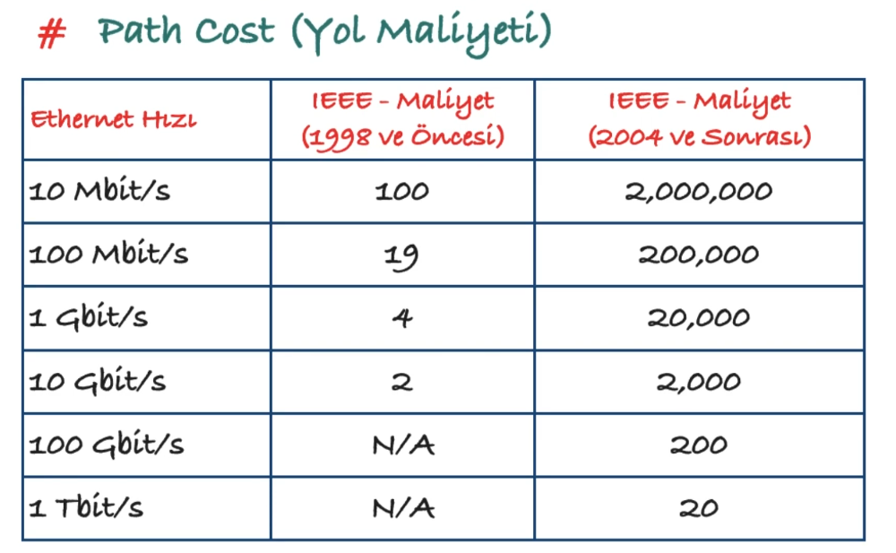
STP Path Cost
Path cost values are assigned per interface speed. Lower cost means a more preferred path.
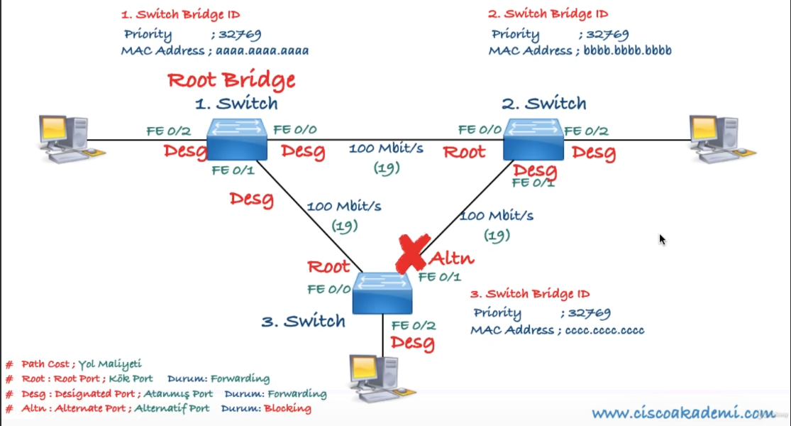
How STP Works
- Elect a Root Bridge — The switch with the lowest Bridge ID wins. There is exactly one Root Bridge per network (per VLAN).
- Select a Root Port on every non-root switch — The port with the lowest cumulative path cost to the Root Bridge becomes the Root Port.
- Select a Designated Port on every segment — On each network segment, the port with the best path cost toward the Root Bridge is elected as the Designated Port. All remaining ports are put into blocking state.
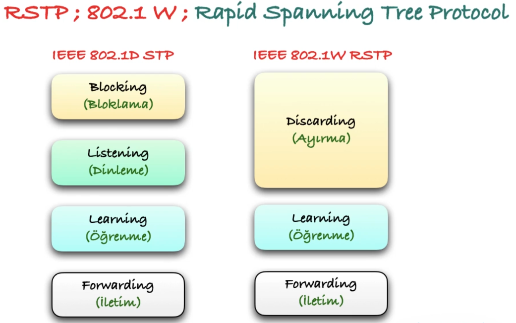
802.1D Port States
| State | Duration | Behavior |
|---|---|---|
| Disabled | — | Port is administratively shut down |
| Blocking | 20 s (Max Age) | Port is active but does not forward traffic; only receives BPDUs |
| Listening | 15 s (Forward Delay) | Sends and receives BPDUs; does not forward user traffic or learn MAC addresses |
| Learning | 15 s (Forward Delay) | Sends and receives BPDUs; learns MAC addresses but does not forward user traffic |
| Forwarding | — | Fully operational; forwards all traffic and updates the MAC table |
| Broken | — | Port detects a configuration or operational problem and drops packets |
The total convergence time from blocking to forwarding is approximately 50 seconds (20 + 15 + 15), which is quite long for modern networks.
STP Timers
| Timer | Default | Description |
|---|---|---|
| Hello Time | 2 s | Interval between BPDU transmissions |
| Forward Delay | 15 s | Time spent in Listening and Learning states |
| Max Age | 20 s | Maximum time a switch stores BPDU information before discarding it |
Timers should only be changed on the Root Bridge:
spanning-tree vlan <vlan-id> hello-time <seconds>
spanning-tree vlan <vlan-id> forward-time <seconds>
spanning-tree vlan <vlan-id> max-age <seconds>
Root Bridge Election
By default, the switch with the lowest MAC address becomes the Root Bridge. In production you should manually assign the Root Bridge — typically the Core switch is primary and the Distribution switch is secondary.
Two methods:
! Method 1 — Set priority directly (must be a multiple of 4096)
spanning-tree vlan 1 priority 4096

! Method 2 — Use the macro (sets priority to 24576 / 28672)
spanning-tree vlan 1 root primary
spanning-tree vlan 1 root secondary
802.1D Acceleration Features
Because 50-second convergence is too slow, Cisco developed proprietary enhancements for 802.1D:
- UplinkFast — Provides fast failover (~1 s) when a root port link fails by immediately activating an alternate port.
spanning-tree uplinkfast - BackboneFast — Reduces convergence by ~20 seconds when an indirect link failure occurs.
spanning-tree backbonefast - PortFast — Skips the Listening and Learning states so the port transitions directly to Forwarding. Only use on ports connected to end devices (PCs, servers, VoIP phones).
spanning-tree portfast
These Cisco-proprietary features have been superseded by RSTP (802.1W), which incorporates their functionality into an open standard.
Rapid Spanning Tree Protocol — RSTP (802.1W)
RSTP dramatically reduces convergence time to approximately 1 second. It was developed by IEEE as an open-standard replacement for Cisco’s UplinkFast, BackboneFast, and PortFast enhancements.
RSTP Port States
| RSTP State | Equivalent 802.1D States | Behavior |
|---|---|---|
| Discarding | Disabled, Blocking, Listening | Port does not forward any traffic; ensures no loop is created |
| Learning | Learning | Learns MAC addresses but does not forward user traffic |
| Forwarding | Forwarding | Fully operational; forwards all traffic |
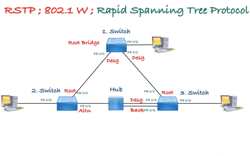
RSTP Port Roles
- Root Port (RP) — Best path to the Root Bridge (one per switch per VLAN).
- Designated Port (DP) — Forwards BPDUs toward other switches on a segment.
- Alternate Port — A backup path to the Root Bridge through a different switch (replaces UplinkFast).
- Backup Port — A redundant path to the Root Bridge on the same switch (rare, used with hubs).
RSTP Port Types
- Edge Port — Connected to a single end device; no risk of loops. Equivalent to a PortFast-enabled port.
- Root Port — Port with the best path cost to the Root Bridge.
- Point-to-Point Port — Any full-duplex port connected to another switch. Full-duplex links guarantee only two devices on the segment, enabling rapid transition.
Enabling RSTP
spanning-tree mode rapid-pvstMultiple Spanning Tree Protocol — MST (802.1S)
In networks with many VLANs, running a separate STP instance per VLAN (as PVST+ or Rapid-PVST+ do) wastes CPU and memory. MST solves this by letting you group multiple VLANs into a smaller number of MST instances. All VLANs mapped to the same instance share a single spanning-tree topology.
Key Concepts
- MST Region — A group of switches that share the same region name, revision number, and VLAN-to-instance mapping. Switches with mismatched parameters are treated as being in different regions.
- IST (Internal Spanning Tree) — Instance 0 — The default instance that carries all VLANs not explicitly mapped to another instance. It also communicates with switches outside the MST region (e.g., those running PVST+ or plain STP).
- MSTI (MST Instance) — A user-defined instance (1–15 on Cisco, up to 64 per IEEE) to which you map specific VLANs.
Why Use MST?
| Scenario | PVST+ / Rapid-PVST+ | MST |
|---|---|---|
| 100 VLANs | 100 STP instances | As few as 2–3 instances |
| CPU / memory usage | High | Low |
| Load balancing | Per-VLAN root placement | Per-instance root placement |
| Interoperability | Cisco only (PVST+) | IEEE open standard |
MST Configuration
! Enter MST configuration mode
spanning-tree mode mst

spanning-tree mst configuration
 name MY-REGION
 revision 1
 instance 1 vlan 10,20,30
 instance 2 vlan 40,50,60
 exit

! Set root priority per instance
spanning-tree mst 0 priority 4096
spanning-tree mst 1 priority 4096
spanning-tree mst 2 priority 8192
Important: All switches in the same MST region must have an identical name, revision number, and VLAN-to-instance mapping. A single mismatch causes the switch to be seen as a separate region.
Verification
show spanning-tree mst configuration
show spanning-tree mst 0
show spanning-tree mst 1
Advanced STP Features
Root Guard
Root Guard prevents a port from becoming a Root Port. If a superior BPDU is received on a Root Guard-enabled port, the port is placed into root-inconsistent (ErrDisabled) state. This protects against misconfigured or rogue switches attempting to take over as Root Bridge.
Place Root Guard on Designated Ports that face switches which should never become the Root Bridge (e.g., Distribution downlinks toward Access switches).
interface GigabitEthernet0/2
 spanning-tree guard root
PortFast
PortFast causes a port to skip the Listening and Learning states and transition directly to Forwarding. It should only be used on ports connected to end devices (PCs, servers, VoIP phones) — never on switch-to-switch links.
! Per-interface
interface GigabitEthernet0/1
 spanning-tree portfast

! For trunk ports connected to a single host (e.g., ESXi server)
interface GigabitEthernet0/2
 spanning-tree portfast trunk

! Globally (applies to all access ports)
spanning-tree portfast default

! Disable on a specific port
interface GigabitEthernet0/8
 spanning-tree portfast disable
BPDU Guard
BPDU Guard shuts down a PortFast-enabled port if it receives a BPDU. This prevents an unauthorized switch from being connected to an access port and accidentally creating a loop.
! Globally (applies to all PortFast-enabled ports)
spanning-tree portfast bpduguard default

! Per-interface
interface GigabitEthernet0/1
 spanning-tree bpduguard enable
When a port is shut down by BPDU Guard, it enters err-disabled state. To recover:
! Manual recovery
interface GigabitEthernet0/1
 shutdown
 no shutdown

! Automatic recovery
errdisable recovery cause bpduguard
errdisable recovery interval <seconds>

! Verify
show errdisable recovery
show interfaces status err-disabled
BPDU Filter
BPDU Filter prevents BPDUs from being sent or received on a port. Use with caution — it effectively disables STP on that port.
! Globally (applies to PortFast-enabled ports only)
spanning-tree portfast bpdufilter default

! Per-interface
interface GigabitEthernet0/6
 spanning-tree bpdufilter enable
Loop Guard
Loop Guard prevents an alternate or root port from becoming a designated port if BPDUs stop being received (e.g., due to a unidirectional link failure). The port is placed into loop-inconsistent state instead.
Do not enable Loop Guard on PortFast-enabled ports.
! Globally
spanning-tree loopguard default

! Per-interface
interface GigabitEthernet0/4
 spanning-tree guard loop
View inconsistent ports:
show spanning-tree inconsistentportsEtherChannel
EtherChannel bundles up to 8 physical links between switches into a single logical link, providing both redundancy and increased bandwidth without STP blocking individual member ports.
STP and FHRP Alignment
First Hop Redundancy Protocols (HSRP, VRRP, GLBP) and STP both deal with redundancy, but at different layers. If they are not aligned, traffic can take suboptimal paths — for example, a host sends traffic to the HSRP active router on Switch A, but STP’s Root Bridge is on Switch B, forcing frames to traverse an extra hop.
The Problem
Consider two Distribution switches providing a default gateway via HSRP:
- DIST-SW-01 is the HSRP Active router for VLAN 10.
- DIST-SW-02 is the STP Root Bridge for VLAN 10.
Hosts in VLAN 10 send traffic to DIST-SW-01 (HSRP active), but Layer 2 frames must first travel toward DIST-SW-02 (Root Bridge) before reaching DIST-SW-01. This creates an unnecessary extra hop and wastes inter-switch bandwidth.
The Solution — Align Root Bridge with FHRP Active/Master
The switch that is the HSRP Active (or VRRP Master, or GLBP AVG) for a given VLAN should also be the STP Root Bridge for that VLAN. This ensures Layer 2 and Layer 3 forwarding paths are consistent.
A common design pattern with per-VLAN load balancing:
| VLAN | STP Root (Primary) | HSRP Active | STP Root (Secondary) | HSRP Standby |
|---|---|---|---|---|
| VLAN 10 | DIST-SW-01 | DIST-SW-01 | DIST-SW-02 | DIST-SW-02 |
| VLAN 20 | DIST-SW-02 | DIST-SW-02 | DIST-SW-01 | DIST-SW-01 |
Configuration Example
! DIST-SW-01
spanning-tree vlan 10 root primary
spanning-tree vlan 20 root secondary

interface vlan 10
 ip address 10.0.10.2 255.255.255.0
 standby 10 ip 10.0.10.1
 standby 10 priority 110
 standby 10 preempt

interface vlan 20
 ip address 10.0.20.2 255.255.255.0
 standby 20 ip 10.0.20.1
 standby 20 priority 90

! DIST-SW-02
spanning-tree vlan 10 root secondary
spanning-tree vlan 20 root primary

interface vlan 10
 ip address 10.0.10.3 255.255.255.0
 standby 10 ip 10.0.10.1
 standby 10 priority 90

interface vlan 20
 ip address 10.0.20.3 255.255.255.0
 standby 20 ip 10.0.20.1
 standby 20 priority 110
 standby 20 preempt
Key Takeaways
- Always align the STP Root Bridge and FHRP active/master on the same switch per VLAN.
- Use per-VLAN root placement (PVST+/Rapid-PVST+) to load-balance traffic across both Distribution switches.
- Enable preempt on the FHRP primary so it reclaims the active role after a failure/recovery — matching STP’s root re-election behavior.
- If using GLBP, all gateways forward traffic simultaneously, so ensure STP paths are optimal toward all AVF (Active Virtual Forwarder) switches.
Production Configuration Example
Core Switch (Root Bridge)
hostname CORE-SW-01

spanning-tree mode rapid-pvst

! Primary Root Bridge for all VLANs
spanning-tree vlan 1-4094 priority 4096

! Timers — only configure on the Root Bridge
spanning-tree vlan 1-4094 hello-time 2
spanning-tree vlan 1-4094 forward-time 15
spanning-tree vlan 1-4094 max-age 20

! Global Loop Guard
spanning-tree loopguard default

! Downlinks to Distribution switches
interface range GigabitEthernet1/0/1-4
 description DOWNLINK-TO-DIST
 switchport mode trunk
 switchport trunk allowed vlan all
 spanning-tree guard loop
 no spanning-tree portfast
 no shutdown

! WAN / external uplink — Root Guard to protect root election
interface GigabitEthernet1/0/48
 description UPLINK-TO-WAN
 spanning-tree guard root
 no shutdown
Distribution Switch (Secondary Root)
hostname DIST-SW-01

spanning-tree mode rapid-pvst

! Secondary Root — takes over if Core fails
spanning-tree vlan 1-4094 priority 28672

spanning-tree loopguard default

! Uplinks to Core
interface range GigabitEthernet1/0/1-2
 description UPLINK-TO-CORE
 switchport mode trunk
 switchport trunk allowed vlan all
 spanning-tree guard loop
 no spanning-tree portfast
 no shutdown

! Downlinks to Access — Root Guard prevents rogue root
interface range GigabitEthernet1/0/3-24
 description DOWNLINK-TO-ACCESS
 switchport mode trunk
 switchport trunk allowed vlan all
 spanning-tree guard root
 spanning-tree guard loop
 no spanning-tree portfast
 no shutdown
Access Switch
hostname ACCESS-SW-01

spanning-tree mode rapid-pvst

! Highest priority value — never becomes Root Bridge
spanning-tree vlan 1-4094 priority 61440

! Global PortFast and BPDU Guard for access ports
spanning-tree portfast default
spanning-tree portfast bpduguard default

spanning-tree loopguard default

! Uplinks to Distribution
interface GigabitEthernet0/1
 description UPLINK-TO-DIST-SW-01
 switchport mode trunk
 switchport trunk allowed vlan all
 no spanning-tree portfast
 spanning-tree guard loop
 no shutdown

interface GigabitEthernet0/2
 description UPLINK-TO-DIST-SW-02
 switchport mode trunk
 switchport trunk allowed vlan all
 no spanning-tree portfast
 spanning-tree guard loop
 no shutdown

! User ports (PCs, printers)
interface range FastEthernet0/1-20
 description USER-PORT
 switchport mode access
 switchport access vlan 10
 spanning-tree portfast
 spanning-tree bpduguard enable
 no shutdown

! VoIP ports
interface range FastEthernet0/21-22
 description VOIP-PORT
 switchport mode access
 switchport access vlan 10
 switchport voice vlan 20
 spanning-tree portfast
 spanning-tree bpduguard enable
 no shutdown

! Server ports — BPDU Filter instead of Guard (servers may run virtual switches)
interface FastEthernet0/23
 description SERVER-PORT
 switchport mode access
 switchport access vlan 30
 spanning-tree portfast
 spanning-tree bpdufilter enable
 no shutdown

! Unused ports
interface FastEthernet0/24
 description UNUSED
 switchport mode access
 switchport access vlan 999
 spanning-tree portfast
 spanning-tree bpduguard enable
 shutdown
Verification Commands
show spanning-tree summary
show spanning-tree vlan 10
show spanning-tree interface GigabitEthernet0/1 detail
show spanning-tree detail | include ieee|occurs|from|executing
show spanning-tree inconsistentports
show interfaces status err-disabled
Summary Table
| Feature | Core | Distribution | Access |
|---|---|---|---|
| Priority | 4096 | 28672 | 61440 |
| Root Guard | WAN port | Downlinks | — |
| Loop Guard | Global | Global | Global |
| PortFast | — | — | Global (default) |
| BPDU Guard | — | — | Global (default) |
| Timer config | Yes (only here) | — | — |