Hi everyone! In this article, I will briefly explain SPAN, RSPAN, and ERSPAN technologies and demonstrate how to configure each of them through a simple lab setup.
Overview
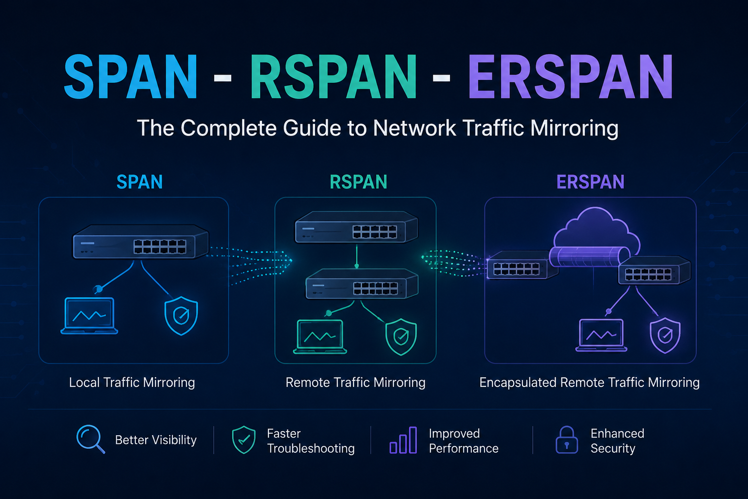
SPAN, RSPAN, and ERSPAN are Cisco technologies used for capturing and forwarding network traffic for analysis. Here is a quick comparison:
| Feature | SPAN | RSPAN | ERSPAN |
|---|---|---|---|
| Scope | Single switch | Multiple switches (Layer 2) | Any IP-routed network (Layer 3) |
| Transport | Local port mirroring | Dedicated VLAN over trunks | GRE encapsulation over IP |
| Use Case | Local troubleshooting | Campus-wide monitoring | Cross-site / WAN / cloud monitoring |
- SPAN (Switched Port Analyzer) — A local mirroring technique that captures traffic from one or more ports on a switch and sends a copy to a locally connected traffic analyzer tool.
- RSPAN (Remote Switched Port Analyzer) — Extends SPAN by allowing traffic from a remote switch to be mirrored and forwarded across the network to a monitoring device through Layer 2 switching infrastructure.
- ERSPAN (Encapsulated Remote Switched Port Analyzer) — Takes it a step further by capturing traffic from a remote device and sending it across a Layer 3 network using GRE encapsulation to a network analyzer, which can also be located remotely.
1. SPAN — Local Port Mirroring
Scope: Single switch.
SPAN (Switched Port Analyzer) is used in Layer 2 networks as a tool for troubleshooting real-time traffic flows. It is also referred to as Port Mirroring or Port Monitoring. Using SPAN, traffic from a port can be duplicated to another port where a network analyzer is connected to capture packets for troubleshooting and analyzing network utilization or performance.
SPAN copies traffic from one or more ports, EtherChannels, or VLANs and sends the copied traffic to one or more destinations for analysis. SPAN does not affect the switching of traffic on source ports.
Configuration
SW1(config)# monitor session 1 source interface GigabitEthernet0/0
SW1(config)# monitor session 1 source interface GigabitEthernet0/2
SW1(config)# monitor session 1 destination interface GigabitEthernet0/3
Verification
SW1# show monitor session 1SPAN with VLAN Filtering (Advanced)
You can filter mirrored traffic by VLAN when the source is a trunk port:
SW1(config)# monitor session 2 source interface range GigabitEthernet1/0/1-5
SW1(config)# monitor session 2 filter vlan 10,20,30
SW1(config)# monitor session 2 destination interface GigabitEthernet1/0/48
2. RSPAN — Remote SPAN (Multi-Switch, Layer 2)
Scope: Multiple switches in the same Layer 2 domain, connected via trunks.
RSPAN works by mirroring the traffic from the source ports of an RSPAN session onto a dedicated VLAN. This VLAN is then trunked to other switches, allowing session traffic to be transported across multiple switches. On the switch containing the destination port, traffic from the RSPAN VLAN is mirrored out to the destination port.
Configuration (Source Switch → Destination Switch)
Step 1 — Create RSPAN VLAN on ALL switches (including intermediate ones):
Switch(config)# vlan 999
Switch(config-vlan)# name RSPAN_VLAN
Switch(config-vlan)# remote-span          ! This is the key command
Switch(config-vlan)# exit
Step 2 — Source Switch: Mirror traffic into the RSPAN VLAN:
SW1(config)# monitor session 1 source interface GigabitEthernet1/0/5 both
SW1(config)# monitor session 1 destination remote vlan 999
Step 3 — Allow RSPAN VLAN on all trunk links:
Switch(config)# interface range GigabitEthernet1/0/23-24
Switch(config-if-range)# switchport trunk allowed vlan add 999
Step 4 — Destination Switch: Receive from RSPAN VLAN and forward to sniffer:
SW2(config)# monitor session 1 source remote vlan 999
SW2(config)# monitor session 1 destination interface GigabitEthernet0/2
RSPAN Verification
Switch# show monitor session 1
Switch# show vlan id 999
3. ERSPAN — Encapsulated Remote SPAN (Layer 3, Cross-Site)
Scope: Any IP-routed network — across data centers, WAN, or cloud.
ERSPAN allows traffic mirroring across Layer 3 networks using Generic Routing Encapsulation (GRE). The source switch encapsulates mirrored traffic in GRE and sends it to a destination IP. The destination switch decapsulates the traffic and sends it to a monitoring device, enabling traffic monitoring over WANs and routed networks.
Note: ERSPAN is a Cisco proprietary feature available on Catalyst 6500, 7600, Nexus, and ASR 1000 platforms.
ERSPAN Configuration
Source Switch (where traffic originates):
SW1(config)# monitor session 1 type erspan-source
SW1(config-mon-erspan-src)# source interface GigabitEthernet0/1 both
SW1(config-mon-erspan-src)# no shutdown
SW1(config-mon-erspan-src)# destination
SW1(config-mon-erspan-src-dst)# erspan-id 100              ! Must match on both ends
SW1(config-mon-erspan-src-dst)# ip address 10.1.1.2        ! IP of destination switch
SW1(config-mon-erspan-src-dst)# origin ip address 10.1.1.1 ! IP of this switch
SW1(config-mon-erspan-src-dst)# exit
Destination Switch (where sniffer is connected):
SW2(config)# monitor session 1 type erspan-destination
SW2(config-mon-erspan-dst)# destination interface GigabitEthernet0/2
SW2(config-mon-erspan-dst)# source
SW2(config-mon-erspan-dst-src)# erspan-id 100              ! Must match source
SW2(config-mon-erspan-dst-src)# ip address 10.1.1.2        ! This switch's IP
SW2(config-mon-erspan-dst-src)# exit
ERSPAN Verification
Switch# show monitor session 1
Switch# show platform hardware qfp active feature erspan state
Thanks for taking time to read this article, I hope you’ll find it useful.
Keep up the great work!