This lab builds a full MPLS L3VPN service across an ISP core (AS 35500) with OSPF Area 0 as the IGP, LDP for label distribution, and MP-BGP (VPNv4) for customer route exchange. Two VPNs — RED (AS 25942) and BLUE (AS 48273) — carry overlapping address space through the same physical infrastructure, demonstrating VRF isolation.
Key design choices:
- P1 and P4 act as BGP Route Reflectors — PEs only peer with these two, no full-mesh iBGP required
as-overrideon all PE-CE peerings since both RED CEs share an AS and both BLUE CEs share an AS- OSPF point-to-point network type on all /30 core links (skips DR/BDR election)
- All BGP loopback peerings use update-source Loopback0
Here is the topology:
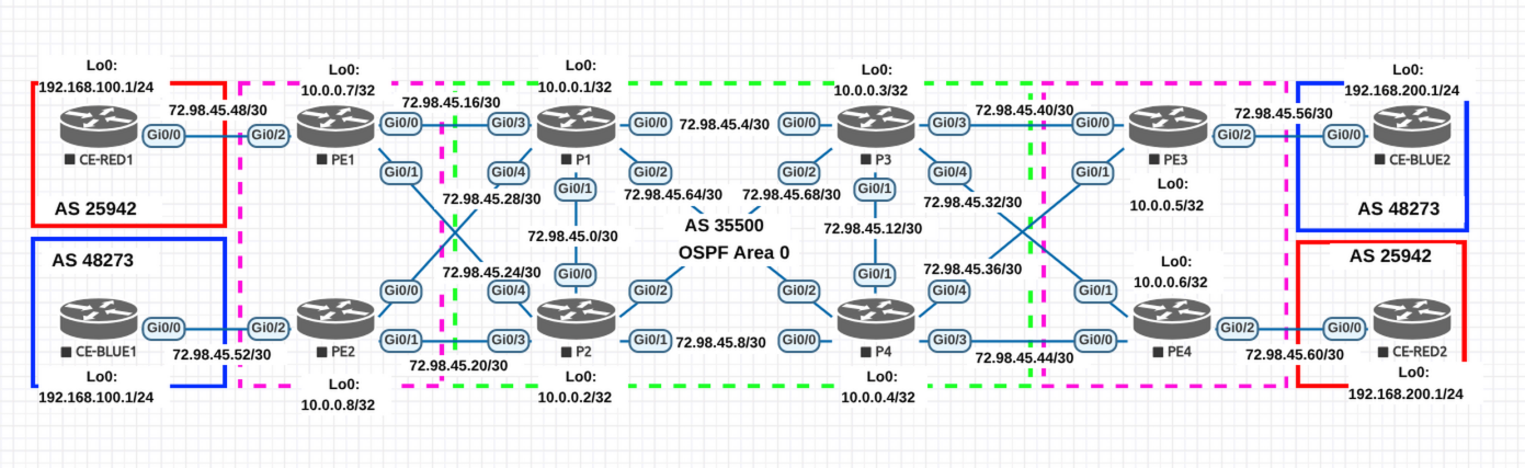
Note: Interface numbers below are based on the topology diagram. Verify they match your EVE-NG wiring before pasting configs.
Addressing Reference
Loopbacks
| Device | Loopback0 | Role |
|---|---|---|
| PE1 | 10.0.0.7/32 | PE — VRF RED |
| PE2 | 10.0.0.8/32 | PE — VRF BLUE |
| P1 | 10.0.0.1/32 | P / Route Reflector |
| P2 | 10.0.0.2/32 | P |
| P3 | 10.0.0.3/32 | P |
| P4 | 10.0.0.4/32 | P / Route Reflector |
| PE3 | 10.0.0.5/32 | PE — VRF BLUE |
| PE4 | 10.0.0.6/32 | PE — VRF RED |
| CE-RED1 | 192.168.100.1/32 | Customer RED site 1 |
| CE-RED2 | 192.168.200.1/32 | Customer RED site 2 |
| CE-BLUE1 | 192.168.100.1/32 | Customer BLUE site 1 |
| CE-BLUE2 | 192.168.200.1/32 | Customer BLUE site 2 |
Core Links (OSPF + MPLS)
| Link | Subnet | Device A — IP | Device B — IP |
|---|---|---|---|
| P1 ↔ P2 | 72.98.45.0/30 | P1 Gi0/1 — .1 | P2 Gi0/0 — .2 |
| P1 ↔ P3 | 72.98.45.4/30 | P1 Gi0/0 — .5 | P3 Gi0/0 — .6 |
| P2 ↔ P4 | 72.98.45.8/30 | P2 Gi0/1 — .9 | P4 Gi0/0 — .10 |
| P3 ↔ P4 | 72.98.45.12/30 | P3 Gi0/1 — .13 | P4 Gi0/1 — .14 |
| PE1 ↔ P1 | 72.98.45.16/30 | P1 Gi0/3 — .17 | PE1 Gi0/0 — .18 |
| PE2 ↔ P2 | 72.98.45.20/30 | P2 Gi0/3 — .21 | PE2 Gi0/1 — .22 |
| PE1 ↔ P2 | 72.98.45.24/30 | P2 Gi0/4 — .25 | PE1 Gi0/1 — .26 |
| PE2 ↔ P1 | 72.98.45.28/30 | P1 Gi0/4 — .29 | PE2 Gi0/0 — .30 |
| PE4 ↔ P3 | 72.98.45.32/30 | P3 Gi0/4 — .33 | PE4 Gi0/1 — .34 |
| PE3 ↔ P4 | 72.98.45.36/30 | P4 Gi0/4 — .37 | PE3 Gi0/1 — .38 |
| PE3 ↔ P3 | 72.98.45.40/30 | P3 Gi0/3 — .41 | PE3 Gi0/0 — .42 |
| PE4 ↔ P4 | 72.98.45.44/30 | P4 Gi0/3 — .45 | PE4 Gi0/0 — .46 |
| P1 ↔ P4 | 72.98.45.64/30 | P1 Gi0/2 — .65 | P4 Gi0/2 — .66 |
| P2 ↔ P3 | 72.98.45.68/30 | P2 Gi0/2 — .69 | P3 Gi0/2 — .70 |
PE-CE Links (VRF, no OSPF/MPLS)
| Link | Subnet | PE — IP | CE — IP | VRF |
|---|---|---|---|---|
| PE1 ↔ CE-RED1 | 72.98.45.48/30 | PE1 Gi0/2 — .49 | CE-RED1 Gi0/0 — .50 | RED |
| PE2 ↔ CE-BLUE1 | 72.98.45.52/30 | PE2 Gi0/2 — .53 | CE-BLUE1 Gi0/0 — .54 | BLUE |
| PE3 ↔ CE-BLUE2 | 72.98.45.56/30 | PE3 Gi0/2 — .57 | CE-BLUE2 Gi0/0 — .58 | BLUE |
| PE4 ↔ CE-RED2 | 72.98.45.60/30 | PE4 Gi0/2 — .61 | CE-RED2 Gi0/0 — .62 | RED |
Configurations
Each phase builds on the previous one. Verify before moving to the next.
Phase 1 — Hostnames, Loopbacks & Core Interfaces
Bring up all core-facing interfaces with IP addresses. No routing protocols yet — just Layer 3 connectivity on directly connected links. CE interfaces are included here too.
Why loopbacks first? Everything else (OSPF router-id, LDP router-id, BGP peering) depends on them.
P1
hostname P1
!
ip cef
!
interface Loopback0
 ip address 10.0.0.1 255.255.255.255
!
interface GigabitEthernet0/0
 description to P3
 ip address 72.98.45.5 255.255.255.252
 no shutdown
!
interface GigabitEthernet0/1
 description to P2
 ip address 72.98.45.1 255.255.255.252
 no shutdown
!
interface GigabitEthernet0/2
 description to P4
 ip address 72.98.45.65 255.255.255.252
 no shutdown
!
interface GigabitEthernet0/3
 description to PE1
 ip address 72.98.45.17 255.255.255.252
 no shutdown
!
interface GigabitEthernet0/4
 description to PE2
 ip address 72.98.45.29 255.255.255.252
 no shutdown
P2
hostname P2
!
ip cef
!
interface Loopback0
 ip address 10.0.0.2 255.255.255.255
!
interface GigabitEthernet0/0
 description to P1
 ip address 72.98.45.2 255.255.255.252
 no shutdown
!
interface GigabitEthernet0/1
 description to P4
 ip address 72.98.45.9 255.255.255.252
 no shutdown
!
interface GigabitEthernet0/2
 description to P3
 ip address 72.98.45.69 255.255.255.252
 no shutdown
!
interface GigabitEthernet0/3
 description to PE2
 ip address 72.98.45.21 255.255.255.252
 no shutdown
!
interface GigabitEthernet0/4
 description to PE1
 ip address 72.98.45.25 255.255.255.252
 no shutdown
P3
hostname P3
!
ip cef
!
interface Loopback0
 ip address 10.0.0.3 255.255.255.255
!
interface GigabitEthernet0/0
 description to P1
 ip address 72.98.45.6 255.255.255.252
 no shutdown
!
interface GigabitEthernet0/1
 description to P4
 ip address 72.98.45.13 255.255.255.252
 no shutdown
!
interface GigabitEthernet0/2
 description to P2
 ip address 72.98.45.70 255.255.255.252
 no shutdown
!
interface GigabitEthernet0/3
 description to PE3
 ip address 72.98.45.41 255.255.255.252
 no shutdown
!
interface GigabitEthernet0/4
 description to PE4
 ip address 72.98.45.33 255.255.255.252
 no shutdown
P4
hostname P4
!
ip cef
!
interface Loopback0
 ip address 10.0.0.4 255.255.255.255
!
interface GigabitEthernet0/0
 description to P2
 ip address 72.98.45.10 255.255.255.252
 no shutdown
!
interface GigabitEthernet0/1
 description to P3
 ip address 72.98.45.14 255.255.255.252
 no shutdown
!
interface GigabitEthernet0/2
 description to P1
 ip address 72.98.45.66 255.255.255.252
 no shutdown
!
interface GigabitEthernet0/3
 description to PE4
 ip address 72.98.45.45 255.255.255.252
 no shutdown
!
interface GigabitEthernet0/4
 description to PE3
 ip address 72.98.45.37 255.255.255.252
 no shutdown
PE1
hostname PE1
!
ip cef
!
interface Loopback0
 ip address 10.0.0.7 255.255.255.255
!
interface GigabitEthernet0/0
 description to P1
 ip address 72.98.45.18 255.255.255.252
 no shutdown
!
interface GigabitEthernet0/1
 description to P2
 ip address 72.98.45.26 255.255.255.252
 no shutdown
PE2
hostname PE2
!
ip cef
!
interface Loopback0
 ip address 10.0.0.8 255.255.255.255
!
interface GigabitEthernet0/0
 description to P1
 ip address 72.98.45.30 255.255.255.252
 no shutdown
!
interface GigabitEthernet0/1
 description to P2
 ip address 72.98.45.22 255.255.255.252
 no shutdown
PE3
hostname PE3
!
ip cef
!
interface Loopback0
 ip address 10.0.0.5 255.255.255.255
!
interface GigabitEthernet0/0
 description to P3
 ip address 72.98.45.42 255.255.255.252
 no shutdown
!
interface GigabitEthernet0/1
 description to P4
 ip address 72.98.45.38 255.255.255.252
 no shutdown
PE4
hostname PE4
!
ip cef
!
interface Loopback0
 ip address 10.0.0.6 255.255.255.255
!
interface GigabitEthernet0/0
 description to P4
 ip address 72.98.45.46 255.255.255.252
 no shutdown
!
interface GigabitEthernet0/1
 description to P3
 ip address 72.98.45.34 255.255.255.252
 no shutdown
CE-RED1
hostname CE-RED1
!
interface Loopback0
 ip address 192.168.100.1 255.255.255.255
!
interface GigabitEthernet0/0
 description to PE1
 ip address 72.98.45.50 255.255.255.252
 no shutdown
CE-RED2
hostname CE-RED2
!
interface Loopback0
 ip address 192.168.200.1 255.255.255.255
!
interface GigabitEthernet0/0
 description to PE4
 ip address 72.98.45.62 255.255.255.252
 no shutdown
CE-BLUE1
hostname CE-BLUE1
!
interface Loopback0
 ip address 192.168.100.1 255.255.255.255
!
interface GigabitEthernet0/0
 description to PE2
 ip address 72.98.45.54 255.255.255.252
 no shutdown
CE-BLUE2
hostname CE-BLUE2
!
interface Loopback0
 ip address 192.168.200.1 255.255.255.255
!
interface GigabitEthernet0/0
 description to PE3
 ip address 72.98.45.58 255.255.255.252
 no shutdown
Verify Phase 1
Ping each directly connected neighbor on every link. Example from P1:
ping 72.98.45.2
ping 72.98.45.6
ping 72.98.45.66
ping 72.98.45.18
ping 72.98.45.30
If a ping fails, check show ip interface brief — the interface may be down or miswired in EVE-NG.
Phase 2 — OSPF (IGP)
Enable OSPF Area 0 on all core interfaces and loopbacks. This gives every router reachability to every other loopback — which is required for LDP and BGP to work later.
We use ip ospf network point-to-point on all /30 links to skip DR/BDR election (faster convergence, cleaner adjacencies).
Important: Do NOT enable OSPF on PE-CE interfaces. Those belong to the customer, not the ISP core.
P1
interface Loopback0
 ip ospf 1 area 0
!
interface GigabitEthernet0/0
 ip ospf network point-to-point
 ip ospf 1 area 0
!
interface GigabitEthernet0/1
 ip ospf network point-to-point
 ip ospf 1 area 0
!
interface GigabitEthernet0/2
 ip ospf network point-to-point
 ip ospf 1 area 0
!
interface GigabitEthernet0/3
 ip ospf network point-to-point
 ip ospf 1 area 0
!
interface GigabitEthernet0/4
 ip ospf network point-to-point
 ip ospf 1 area 0
!
router ospf 1
 router-id 10.0.0.1
 mpls ldp sync
P2
interface Loopback0
 ip ospf 1 area 0
!
interface GigabitEthernet0/0
 ip ospf network point-to-point
 ip ospf 1 area 0
!
interface GigabitEthernet0/1
 ip ospf network point-to-point
 ip ospf 1 area 0
!
interface GigabitEthernet0/2
 ip ospf network point-to-point
 ip ospf 1 area 0
!
interface GigabitEthernet0/3
 ip ospf network point-to-point
 ip ospf 1 area 0
!
interface GigabitEthernet0/4
 ip ospf network point-to-point
 ip ospf 1 area 0
!
router ospf 1
 router-id 10.0.0.2
 mpls ldp sync
P3
interface Loopback0
 ip ospf 1 area 0
!
interface GigabitEthernet0/0
 ip ospf network point-to-point
 ip ospf 1 area 0
!
interface GigabitEthernet0/1
 ip ospf network point-to-point
 ip ospf 1 area 0
!
interface GigabitEthernet0/2
 ip ospf network point-to-point
 ip ospf 1 area 0
!
interface GigabitEthernet0/3
 ip ospf network point-to-point
 ip ospf 1 area 0
!
interface GigabitEthernet0/4
 ip ospf network point-to-point
 ip ospf 1 area 0
!
router ospf 1
 router-id 10.0.0.3
 mpls ldp sync
P4
interface Loopback0
 ip ospf 1 area 0
!
interface GigabitEthernet0/0
 ip ospf network point-to-point
 ip ospf 1 area 0
!
interface GigabitEthernet0/1
 ip ospf network point-to-point
 ip ospf 1 area 0
!
interface GigabitEthernet0/2
 ip ospf network point-to-point
 ip ospf 1 area 0
!
interface GigabitEthernet0/3
 ip ospf network point-to-point
 ip ospf 1 area 0
!
interface GigabitEthernet0/4
 ip ospf network point-to-point
 ip ospf 1 area 0
!
router ospf 1
 router-id 10.0.0.4
 mpls ldp sync
PE1
interface Loopback0
 ip ospf 1 area 0
!
interface GigabitEthernet0/0
 ip ospf network point-to-point
 ip ospf 1 area 0
!
interface GigabitEthernet0/1
 ip ospf network point-to-point
 ip ospf 1 area 0
!
router ospf 1
 router-id 10.0.0.7
 mpls ldp sync
PE2
interface Loopback0
 ip ospf 1 area 0
!
interface GigabitEthernet0/0
 ip ospf network point-to-point
 ip ospf 1 area 0
!
interface GigabitEthernet0/1
 ip ospf network point-to-point
 ip ospf 1 area 0
!
router ospf 1
 router-id 10.0.0.8
 mpls ldp sync
PE3
interface Loopback0
 ip ospf 1 area 0
!
interface GigabitEthernet0/0
 ip ospf network point-to-point
 ip ospf 1 area 0
!
interface GigabitEthernet0/1
 ip ospf network point-to-point
 ip ospf 1 area 0
!
router ospf 1
 router-id 10.0.0.5
 mpls ldp sync
PE4
interface Loopback0
 ip ospf 1 area 0
!
interface GigabitEthernet0/0
 ip ospf network point-to-point
 ip ospf 1 area 0
!
interface GigabitEthernet0/1
 ip ospf network point-to-point
 ip ospf 1 area 0
!
router ospf 1
 router-id 10.0.0.6
 mpls ldp sync
Verify Phase 2
From any core router:
show ip ospf neighborEvery neighbor should be in FULL state. Point-to-point links go directly to FULL (no DR/BDR).
show ip route ospfAll 8 loopbacks (10.0.0.1–10.0.0.8) and all /30 transit subnets should appear. If a loopback is missing, check that router’s ip ospf 1 area 0 on Loopback0.
Phase 3 — MPLS / LDP
Enable LDP on all core interfaces. LDP builds label bindings for every IGP-learned /32 prefix, creating LSPs (Label Switched Paths) across the core.
mpls ldp router-id Loopback0 force ensures LDP uses the stable loopback IP (same one OSPF advertises) as its transport address. Without force, LDP might pick a physical interface IP if it comes up first.
Important: Do NOT enable
mpls ipon PE-CE interfaces. MPLS is only for the ISP core.
P1
interface GigabitEthernet0/0
 mpls ip
!
interface GigabitEthernet0/1
 mpls ip
!
interface GigabitEthernet0/2
 mpls ip
!
interface GigabitEthernet0/3
 mpls ip
!
interface GigabitEthernet0/4
 mpls ip
!
mpls label protocol ldp
mpls ldp router-id Loopback0 force
mpls ldp session protection
P2
interface GigabitEthernet0/0
 mpls ip
!
interface GigabitEthernet0/1
 mpls ip
!
interface GigabitEthernet0/2
 mpls ip
!
interface GigabitEthernet0/3
 mpls ip
!
interface GigabitEthernet0/4
 mpls ip
!
mpls label protocol ldp
mpls ldp router-id Loopback0 force
mpls ldp session protection
P3
interface GigabitEthernet0/0
 mpls ip
!
interface GigabitEthernet0/1
 mpls ip
!
interface GigabitEthernet0/2
 mpls ip
!
interface GigabitEthernet0/3
 mpls ip
!
interface GigabitEthernet0/4
 mpls ip
!
mpls label protocol ldp
mpls ldp router-id Loopback0 force
mpls ldp session protection
P4
interface GigabitEthernet0/0
 mpls ip
!
interface GigabitEthernet0/1
 mpls ip
!
interface GigabitEthernet0/2
 mpls ip
!
interface GigabitEthernet0/3
 mpls ip
!
interface GigabitEthernet0/4
 mpls ip
!
mpls label protocol ldp
mpls ldp router-id Loopback0 force
mpls ldp session protection
PE1
interface GigabitEthernet0/0
 mpls ip
!
interface GigabitEthernet0/1
 mpls ip
!
mpls label protocol ldp
mpls ldp router-id Loopback0 force
mpls ldp session protection
PE2
interface GigabitEthernet0/0
 mpls ip
!
interface GigabitEthernet0/1
 mpls ip
!
mpls label protocol ldp
mpls ldp router-id Loopback0 force
mpls ldp session protection
PE3
interface GigabitEthernet0/0
 mpls ip
!
interface GigabitEthernet0/1
 mpls ip
!
mpls label protocol ldp
mpls ldp router-id Loopback0 force
mpls ldp session protection
PE4
interface GigabitEthernet0/0
 mpls ip
!
interface GigabitEthernet0/1
 mpls ip
!
mpls label protocol ldp
mpls ldp router-id Loopback0 force
mpls ldp session protection
Verify Phase 3
show mpls ldp neighborEach router should have an LDP neighbor for every directly connected core peer. Transport addresses should be Loopback0 IPs. P routers should each have 5 LDP neighbors; PEs should each have 2.
show mpls forwarding-tableShould show label bindings for all /32 loopback prefixes.
traceroute 10.0.0.5 source Loopback0The trace should show MPLS labels ([MPLS: Label X Exp 0]). If you only see IP hops, LDP isn’t working on one of the intermediate links.
Phase 4 — VRF Definitions & PE-CE Interfaces
Before BGP can exchange VPN routes, each PE needs a VRF defined and the customer-facing interface placed in that VRF.
Critical order: Apply ip vrf forwarding before ip address on the interface. Adding a VRF to an interface wipes its IP address on Cisco IOS.
- RD (Route Distinguisher): Makes prefixes globally unique in BGP —
35500:100for RED,35500:200for BLUE - RT (Route Target): Controls which VRFs import/export to each other. Same RT value on both RED PEs means they share routes; same for BLUE
PE1 — VRF RED
ip vrf RED
 rd 35500:100
 route-target export 35500:100
 route-target import 35500:100
!
interface GigabitEthernet0/2
 description to CE-RED1
 ip vrf forwarding RED
 ip address 72.98.45.49 255.255.255.252
 no shutdown
PE2 — VRF BLUE
ip vrf BLUE
 rd 35500:200
 route-target export 35500:200
 route-target import 35500:200
!
interface GigabitEthernet0/2
 description to CE-BLUE1
 ip vrf forwarding BLUE
 ip address 72.98.45.53 255.255.255.252
 no shutdown
PE3 — VRF BLUE
ip vrf BLUE
 rd 35500:200
 route-target export 35500:200
 route-target import 35500:200
!
interface GigabitEthernet0/2
 description to CE-BLUE2
 ip vrf forwarding BLUE
 ip address 72.98.45.57 255.255.255.252
 no shutdown
PE4 — VRF RED
ip vrf RED
 rd 35500:100
 route-target export 35500:100
 route-target import 35500:100
!
interface GigabitEthernet0/2
 description to CE-RED2
 ip vrf forwarding RED
 ip address 72.98.45.61 255.255.255.252
 no shutdown
Verify Phase 4
show ip vrfShould list the VRF name with its RD and the assigned interface.
! From PE1
ping vrf RED 72.98.45.50
Should reach CE-RED1 over the VRF link. Repeat on each PE for its CE.
Phase 5 — MP-BGP (VPNv4) on Route Reflectors
P1 and P4 are the route reflectors. They peer with all 4 PEs (as route-reflector-client) and with each other (normal iBGP). They don’t need VRF definitions — they only reflect VPNv4 routes, never install them.
no bgp default ipv4-unicast prevents auto-activation of IPv4 unicast for each neighbor. We only need the VPNv4 address family.
send-community both is mandatory — without it, RT communities (which control VRF import/export) are stripped and the whole L3VPN breaks silently.
P1
router bgp 35500
 bgp router-id 10.0.0.1
 no bgp default ipv4-unicast
 bgp cluster-id 1
 !
 neighbor 10.0.0.4 remote-as 35500
 neighbor 10.0.0.4 update-source Loopback0
 neighbor 10.0.0.4 description P4-RR
 !
 neighbor 10.0.0.5 remote-as 35500
 neighbor 10.0.0.5 update-source Loopback0
 neighbor 10.0.0.5 description PE3
 !
 neighbor 10.0.0.6 remote-as 35500
 neighbor 10.0.0.6 update-source Loopback0
 neighbor 10.0.0.6 description PE4
 !
 neighbor 10.0.0.7 remote-as 35500
 neighbor 10.0.0.7 update-source Loopback0
 neighbor 10.0.0.7 description PE1
 !
 neighbor 10.0.0.8 remote-as 35500
 neighbor 10.0.0.8 update-source Loopback0
 neighbor 10.0.0.8 description PE2
 !
 address-family vpnv4
  neighbor 10.0.0.4 activate
  neighbor 10.0.0.4 send-community both
  !
  neighbor 10.0.0.5 activate
  neighbor 10.0.0.5 send-community both
  neighbor 10.0.0.5 route-reflector-client
  !
  neighbor 10.0.0.6 activate
  neighbor 10.0.0.6 send-community both
  neighbor 10.0.0.6 route-reflector-client
  !
  neighbor 10.0.0.7 activate
  neighbor 10.0.0.7 send-community both
  neighbor 10.0.0.7 route-reflector-client
  !
  neighbor 10.0.0.8 activate
  neighbor 10.0.0.8 send-community both
  neighbor 10.0.0.8 route-reflector-client
 exit-address-family
P4
router bgp 35500
 bgp router-id 10.0.0.4
 no bgp default ipv4-unicast
 bgp cluster-id 1
 !
 neighbor 10.0.0.1 remote-as 35500
 neighbor 10.0.0.1 update-source Loopback0
 neighbor 10.0.0.1 description P1-RR
 !
 neighbor 10.0.0.5 remote-as 35500
 neighbor 10.0.0.5 update-source Loopback0
 neighbor 10.0.0.5 description PE3
 !
 neighbor 10.0.0.6 remote-as 35500
 neighbor 10.0.0.6 update-source Loopback0
 neighbor 10.0.0.6 description PE4
 !
 neighbor 10.0.0.7 remote-as 35500
 neighbor 10.0.0.7 update-source Loopback0
 neighbor 10.0.0.7 description PE1
 !
 neighbor 10.0.0.8 remote-as 35500
 neighbor 10.0.0.8 update-source Loopback0
 neighbor 10.0.0.8 description PE2
 !
 address-family vpnv4
  neighbor 10.0.0.1 activate
  neighbor 10.0.0.1 send-community both
  !
  neighbor 10.0.0.5 activate
  neighbor 10.0.0.5 send-community both
  neighbor 10.0.0.5 route-reflector-client
  !
  neighbor 10.0.0.6 activate
  neighbor 10.0.0.6 send-community both
  neighbor 10.0.0.6 route-reflector-client
  !
  neighbor 10.0.0.7 activate
  neighbor 10.0.0.7 send-community both
  neighbor 10.0.0.7 route-reflector-client
  !
  neighbor 10.0.0.8 activate
  neighbor 10.0.0.8 send-community both
  neighbor 10.0.0.8 route-reflector-client
 exit-address-family
Verify Phase 5
On P1 or P4:
show bgp vpnv4 unicast all summaryThe other RR and all 4 PEs should appear. Sessions will be Active or Idle until the PEs are configured in the next phase — that’s expected.
Phase 6 — MP-BGP (VPNv4) on PEs
Each PE peers with both route reflectors (P1 and P4) for VPNv4, then has a separate address-family ipv4 vrf block for the eBGP session to its local CE.
as-override is needed because both RED CEs share AS 25942 (and both BLUE CEs share AS 48273). Without it, CE-RED1 would reject routes from CE-RED2 — it sees its own AS in the path and treats it as a loop.
PE1
router bgp 35500
 bgp router-id 10.0.0.7
 no bgp default ipv4-unicast
 !
 neighbor 10.0.0.1 remote-as 35500
 neighbor 10.0.0.1 update-source Loopback0
 neighbor 10.0.0.1 description P1-RR
 !
 neighbor 10.0.0.4 remote-as 35500
 neighbor 10.0.0.4 update-source Loopback0
 neighbor 10.0.0.4 description P4-RR
 !
 address-family vpnv4
  neighbor 10.0.0.1 activate
  neighbor 10.0.0.1 send-community both
  neighbor 10.0.0.4 activate
  neighbor 10.0.0.4 send-community both
 exit-address-family
 !
 address-family ipv4 vrf RED
  neighbor 72.98.45.50 remote-as 25942
  neighbor 72.98.45.50 activate
  neighbor 72.98.45.50 as-override
 exit-address-family
PE2
router bgp 35500
 bgp router-id 10.0.0.8
 no bgp default ipv4-unicast
 !
 neighbor 10.0.0.1 remote-as 35500
 neighbor 10.0.0.1 update-source Loopback0
 neighbor 10.0.0.1 description P1-RR
 !
 neighbor 10.0.0.4 remote-as 35500
 neighbor 10.0.0.4 update-source Loopback0
 neighbor 10.0.0.4 description P4-RR
 !
 address-family vpnv4
  neighbor 10.0.0.1 activate
  neighbor 10.0.0.1 send-community both
  neighbor 10.0.0.4 activate
  neighbor 10.0.0.4 send-community both
 exit-address-family
 !
 address-family ipv4 vrf BLUE
  neighbor 72.98.45.54 remote-as 48273
  neighbor 72.98.45.54 activate
  neighbor 72.98.45.54 as-override
 exit-address-family
PE3
router bgp 35500
 bgp router-id 10.0.0.5
 no bgp default ipv4-unicast
 !
 neighbor 10.0.0.1 remote-as 35500
 neighbor 10.0.0.1 update-source Loopback0
 neighbor 10.0.0.1 description P1-RR
 !
 neighbor 10.0.0.4 remote-as 35500
 neighbor 10.0.0.4 update-source Loopback0
 neighbor 10.0.0.4 description P4-RR
 !
 address-family vpnv4
  neighbor 10.0.0.1 activate
  neighbor 10.0.0.1 send-community both
  neighbor 10.0.0.4 activate
  neighbor 10.0.0.4 send-community both
 exit-address-family
 !
 address-family ipv4 vrf BLUE
  neighbor 72.98.45.58 remote-as 48273
  neighbor 72.98.45.58 activate
  neighbor 72.98.45.58 as-override
 exit-address-family
PE4
router bgp 35500
 bgp router-id 10.0.0.6
 no bgp default ipv4-unicast
 !
 neighbor 10.0.0.1 remote-as 35500
 neighbor 10.0.0.1 update-source Loopback0
 neighbor 10.0.0.1 description P1-RR
 !
 neighbor 10.0.0.4 remote-as 35500
 neighbor 10.0.0.4 update-source Loopback0
 neighbor 10.0.0.4 description P4-RR
 !
 address-family vpnv4
  neighbor 10.0.0.1 activate
  neighbor 10.0.0.1 send-community both
  neighbor 10.0.0.4 activate
  neighbor 10.0.0.4 send-community both
 exit-address-family
 !
 address-family ipv4 vrf RED
  neighbor 72.98.45.62 remote-as 25942
  neighbor 72.98.45.62 activate
  neighbor 72.98.45.62 as-override
 exit-address-family
Verify Phase 6
On any PE:
show bgp vpnv4 unicast all summaryTwo neighbors (P1 at 10.0.0.1, P4 at 10.0.0.4) should be in Established state. The PE-CE neighbor will still be Active — the CEs aren’t configured yet.
On the RRs:
show bgp vpnv4 unicast all summaryAll 4 PEs + the other RR should now be Established.
Phase 7 — CE BGP
The final step. Each CE runs a simple eBGP config — advertise its local loopback network and peer with the PE.
CE-RED1
router bgp 25942
 bgp router-id 192.168.100.1
 network 192.168.100.1 mask 255.255.255.255
 neighbor 72.98.45.49 remote-as 35500
CE-RED2
router bgp 25942
 bgp router-id 192.168.200.1
 network 192.168.200.1 mask 255.255.255.255
 neighbor 72.98.45.61 remote-as 35500
CE-BLUE1
router bgp 48273
 bgp router-id 192.168.100.1
 network 192.168.100.1 mask 255.255.255.255
 neighbor 72.98.45.53 remote-as 35500
CE-BLUE2
router bgp 48273
 bgp router-id 192.168.200.1
 network 192.168.200.1 mask 255.255.255.255
 neighbor 72.98.45.57 remote-as 35500
Verify Phase 7
On each PE, check the VRF BGP session came up:
show bgp vpnv4 unicast all summaryThe CE neighbor should now show Established with PfxRcd = 1.
Check VRF routes on PE1:
show ip route vrf REDShould show:
C 72.98.45.48/30— directly connected to CE-RED1B 192.168.100.1/32— learned from CE-RED1 via eBGPB 192.168.200.1/32— learned from PE4 via MP-BGP (next-hop 10.0.0.6)
Final Verification
End-to-End Ping
The ultimate test — ping between customer sites within each VPN:
! From CE-RED1 to CE-RED2's loopback
ping 192.168.200.1 source 192.168.100.1

! From CE-BLUE1 to CE-BLUE2's loopback
ping 192.168.200.1 source 192.168.100.1
Both should succeed. If VRF isolation is correct, CE-RED1 should not be able to reach any BLUE addresses and vice versa.
Confirm VRF Isolation
From PE1, verify RED and BLUE are truly separate:
show ip route vrf RED
show ip route vrf BLUE
PE1 only has VRF RED — the BLUE table shouldn’t exist on PE1. Similarly PE2 only has VRF BLUE.